
Generate New Template
Yep, another airliner post 🫠.
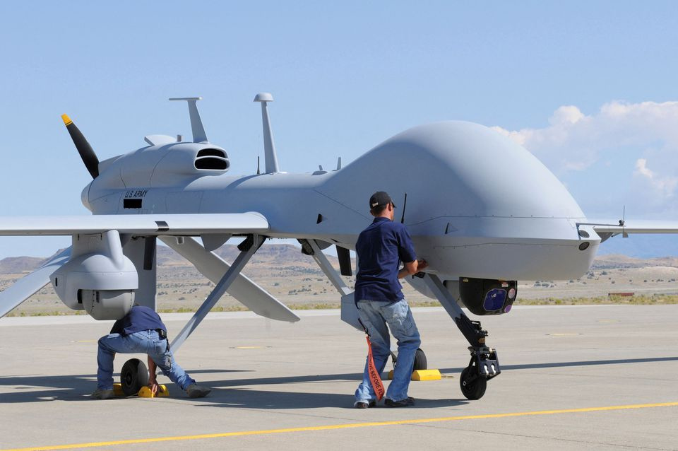
Something that has bothered me is the view from the alleged MQ-1C, as it’s not something I have ever seen before and the orientation of the wing is very confusing with the front of the fuselage in the frame. I decided to emulate it in Blender using an MQ9 model scaled to the dimensions of the MQ1. I don’t know if the chord length of the MQ1 is appreciably shorter than the MQ9 but this scaled model is likely good enough to pass the sniff test.
Blender Setup
Using publicly available information on the dimensions of the MQ-1 I estimated the placement based on this image with sensor balls mounted where munitions are normally present. Given the width of the fuselage is 1m the sensor balls are just about 2m out and 0.3m below the wing: https://i.imgur.com/y0KZSQv.png
Camera Parameters
Note: Backing into camera parameters is not how a simulation is supposed to work, but considering we don’t have any information on the imaging sensor in the video this is less a simulation and more “is this physically possible?”.
Starting with the thermal image size of 960×720 I adjusted the focal length until the scene roughly matches what we see in the video. The obvious difference is the height of the fuselage, but without knowing the true camera parameters (focal length, sensor size, sensor pitch, etc) this will never be a 1:1 simulation.
The most important parameter here is the horizontal field of view, as that’s how most sensor ball specs are advertised alongside the resolution. This scene shows an 80o HFOV which is fairly wide but not out of the realm of possibility. The sensor size here is 46mm which is large but not impossibly large.
To maintain the same view sensor size and HFOV move inversely to each other, so if we assume a smaller sensor we need to increase HFOV, just something to consider.
Summary Comparison
Finally I took the Blender scene, frame from the thermal video, and a colormapped version of the Blender scene and put them all next to each other: https://i.imgur.com/NChncjQ.png
Do not point to the light blue stripe on the Blender “thermal” view and compare it to the orange spot on the thermal frame. Mapping standard RGB to HSV is not the same operation as mapping 16-bit grayscale to what we see in the thermal video. We cannot compare a simulated visible band image with a novel color map and a thermal image, so just don’t.
I don’t know of a free file sharing site but if someone wants the .blend and knows of one I’ll upload it so you can mess with the settings.
submitted by /u/rollingalpine
[link] [comments]